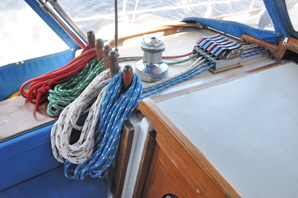
 Rope is used to rotate nearly all sail furling drums, and some, like code-zero furlers and the Hood in-mast system employ a continuous rope loop. The French made Facnor furling drivers on the mainsail and squaresail of Britannia were also operated with rope - Britannia is a brigantine schooner - except they did not have continuous lines, only a single rope passing once around the furling gear then back to the cockpit, resulting in a very long tail on one end or the other as the sails were furled and unfurled.
Britannia’s mainsail had a rope tail of 45’ feet and the squaresail a tail of 35’ feet. Along with two furling head-sail lines and the between-mast staysail furler line, the port side rope-deck had a lot of ropes. If the two longest ones  could be made into continuous loops just long enough to wind round the winch then back again, it would eliminate yards of rope that had to be coiled every time the sails were used.
Rope makers describe various methods in their manuals and web videos about how to make a continuous rope splice in double braided line, but they all result in a splice that is thicker than the rest of the rope. In Britannia’s furling line layout such a splice would not pass through the jaws of the winding drums, the sheaves, or the rope clutches. To be able to use a continuous loop the splice needed to be no thicker than the diameter of the rope, and needless to say, it also had to be very strong. After a lot of experimentation and testing I arrived at a method to splice two ends of a double braided line together, resulting in a uniform thickness the same as the rope, and which has been officially tested to have great strength.
Some rope makers produce hollow core rope, which is easy to join into an end-to-end splice that is the same diameter as the rope, but having no inner core the line is not as strong as double braided rope, and if the load is heavy, like when roller furling a large mainsail into its mast, the splice might not be strong enough.
Nearly all splices result in a weakening of the rope, so this should be considered when deciding where to position a continuous line splice. All sail furlers that use a rope passing through a winding mechanism, (whether a continuous loop or not), have one side of the line - usually the furling line - that needs more “hauling” than the other side. For example: the line winding an in-mast sail back into its mast carries much more strain than when being unfurled, which is done with its out-haul. It is therefore logical to position a continuous loop splice on the least loaded side.
TOOLS.
The following items were used to make the splice:
- A sharp sewing needle and whipping twine: Dyneema whipping twine is best for this operation since it is considerably stronger than regular whipping twine and adds great strength to this type of splice. Available from Miami Cordage Inc. www.miamicordage.com.
- A box cutter, (Stanley knife), with a new sharp blade: Dyneema cannot be cut with scissors.
- A scalpel type knife (Exacto), with a new sharp pointed blade: For stripping out individual rope strands.
- A roll of ¾” masking tape: To stop the rope ends fraying, and that does not leave a glue residue on the rope like electrician's tape.
- A heat-gun: To heat-shrink the tubing.
- A gas lighter: To weld the two ends of the rope core together.
- A one and a half inch, (1½”), length of heat shrink tubing: If a splice has to unavoidably pass through sheaves, blocks or round a winch as mine did, do not use heat-shrink with adhesive in the tube because it sets rigid and inflexible and causes problems as it passes over or through blocks and sheaves. Use non-adhesive heat shrink instead that is more flexible. However, if the splice can be positioned so that it does not pass through any restrictions, then adhesive heat-shrink tubing can be used, since it is stronger and also waterproof. Whichever type is used it should be the correct size to properly shrink on the rope.
MAKING THE SPLICE.
Note: Before making a continuous loop splice, the rope must first be rove through all sheaves, pulleys and clutches, because it cannot be threaded through afterwards, since it will have no ends.
Rope terminology: The cover is the complete outer weave of the rope. The core is the complete inner weave of the rope. A strand is one weave of the cover - usually there are twenty-four strands on a double braided cover, in twelve sets of two.
Like most technical instructions, this splice is more complicated to describe than to actually do. First thoroughly read the instructions to envisage each operation. It would also be beneficial to make a trial splice on a length of spare rope of the same size. Perform each stage slowly and methodically and the result will be a perfect continuous rope loop of great strength.
Simply put, the splice is formed by smoothly interconnecting both ends of the core and cover spaced separately.
 Fig 1. Loosely tape both ends of the cover to stop them fraying, then slide a one and a half inch, (1½”), length of heat-shrink tube down one rope.
 Fig 2. On one rope end, milk the cover back from the core to expose about 40 times the diameter of the rope, (for the ⅜” rope shown this is 15” inches), then tape the core at that point. Prevent the milked cover sliding back over the core by pushing a needle through the rope. Then half an inch, ( ½”) from the tape cut the core off.
 Fig 3. On the other end of the rope, first make sure there is no slack in the cover, then tape the end, but one inch (1”) shorter than the length of the core that has just been cut-off.
 Fig 4. Using a tiny Phillips screwdriver or pic, lift a strand of the cover near the tape and insert a sharp scalpel blade into the opening and sever the strand. Locate the same strand an inch further down the weave and ease it back through the cover out of the way. Continue doing this until the core is exposed enough to be eased completely out of the cover. Be very careful not to nick the core with the knife.

 Fig 5. Having extracted the core from the cover, cut the cover off completely and clean up the frayed ends flush with its tape. Tape the core half an inch ( ½”) from its end.
This will give one rope end with no core and one with no cover.
 Fig 6. Position both cores about half an inch apart ( ½”) and using the gas lighter heat the ends
 ![]() simultaneously until they both melt, then weld them together and with a rubber gloved finger roll the weld back and forth to make a circular joint the same thickness as the core - be aware that the joint will be very hot.
simultaneously until they both melt, then weld them together and with a rubber gloved finger roll the weld back and forth to make a circular joint the same thickness as the core - be aware that the joint will be very hot.
 Fig 7. Starting half an inch from the weld ( ½”) bend a tight half inch wide whipping on either side and leave enough on the whipping twine to make a series of stitches from the outside edge of one whipping, straight across the weld and through the core outside edge on the other side and pull taught - but not too much to deform the joint. Repeat this five times, backwards and forwards, evenly spaced around the core. This whipping technique carries most of the load of the core splice, yet remains flexible as it passes through sheaves and blocks. This completes the core splice.
 Fig 8. Remove the tapes and milk the outer covers together over the core splice until they meet, then place a tight binding of tape over the joint. If the two covers do not meet, unfortunately it will be necessary to shorten the core splice. Unpick it completely, then cut the weld out by the distance the covers were apart, plus half an inch ( ½”). Re-weld and re-whip the core, which will bring the covers together.
 Fig 9. Bend a very tight one inch wide (1”) whipping over the cover joint and tape, then lock-stitch from the outer edge of the whipping through the cover and across the center and through the cover on the other side. Make five passes evenly round and through the rope. This lock-stitches the cover to the core and greatly reinforces the cover joint.
![]() Fig 10. Finally, slide the heat shrink tube over the cover join and using a heat gun shrink it to seal the join, being extra careful not to damage the cover.
Fig 10. Finally, slide the heat shrink tube over the cover join and using a heat gun shrink it to seal the join, being extra careful not to damage the cover.
This is now a continuously looped line with strong splices in both the core and cover, but spaced wide enough apart to act separately.
STRENGTH.
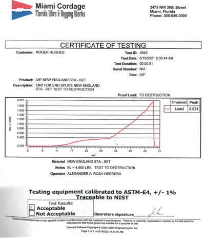
 As with any splice, it would be reassuring to know its strength relative to the tensile strength of the rest of the rope. Tensile strength is the load on which a new rope can be expected to break when tested on approved ASTM, (American Society for Testing Materials) rope testing equipment. The ⅜” inch double braided polyethylene line used here is rated to have a tensile strength of between 3,000 and 3800 lbs., depending on which manufacturer's tables you read.
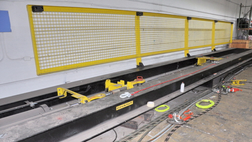
One of my continuous splices was tested by Miami Cordage Inc, a Florida commercial rope maker who  supply the US Navy and make all types of rope, including Dyneema. They have a 40’ foot long hydraulic testing rig that can stretch any rope to destruction, including the massive hawsers used to moor aircraft carriers. My puny ten foot long piece of string with the splice in the middle was stretched until it eventually snapped at 2031 lbs. This is far more than the torque required to rotate the drivers on my two sails and the splices have performed flawlessly thus far. Making continuous loops has greatly simplified the operation of the sails and there is now a much less cluttered cockpit.
Warning: It is inadvisable to use any type of spliced rope for personal safety attachments, like to a bosun's chair or safety harness. This is because any buried splice, even the class-one eye splice, cannot be inspected internally. It is far safer to tie these lines using an appropriate knot.

